Here is the idea behind all this:
The Pi 4 has PciE lines right near the USB 3 ports. PciE extenders commonly
use USB 3 cables to carry the signal. The cables carry the signal but not over the
USB 3 protocol.
So these extenders happen to all use USB 3 and copy the pinout so there is like an
unofficial standard.
This bridge chip takes the place of the USB 3 controller on the PI 4 and routes
the PciE lines to the USB 3 port as in this standard.
Installation requires smd rework with a hot air station.
I'll probably try to do this next week at the regular LUG meeting.
In the photo album see:
1. top of the bridge chip. It is just a 2 layer pcb with some vias to
route lines that cross over.
2. bottom of chip with signal lines that need solder.
3. I bought enough for mistakes and/or give away
4. documentation included
5. pcie extender with 4 port sata controller
6. closeup view
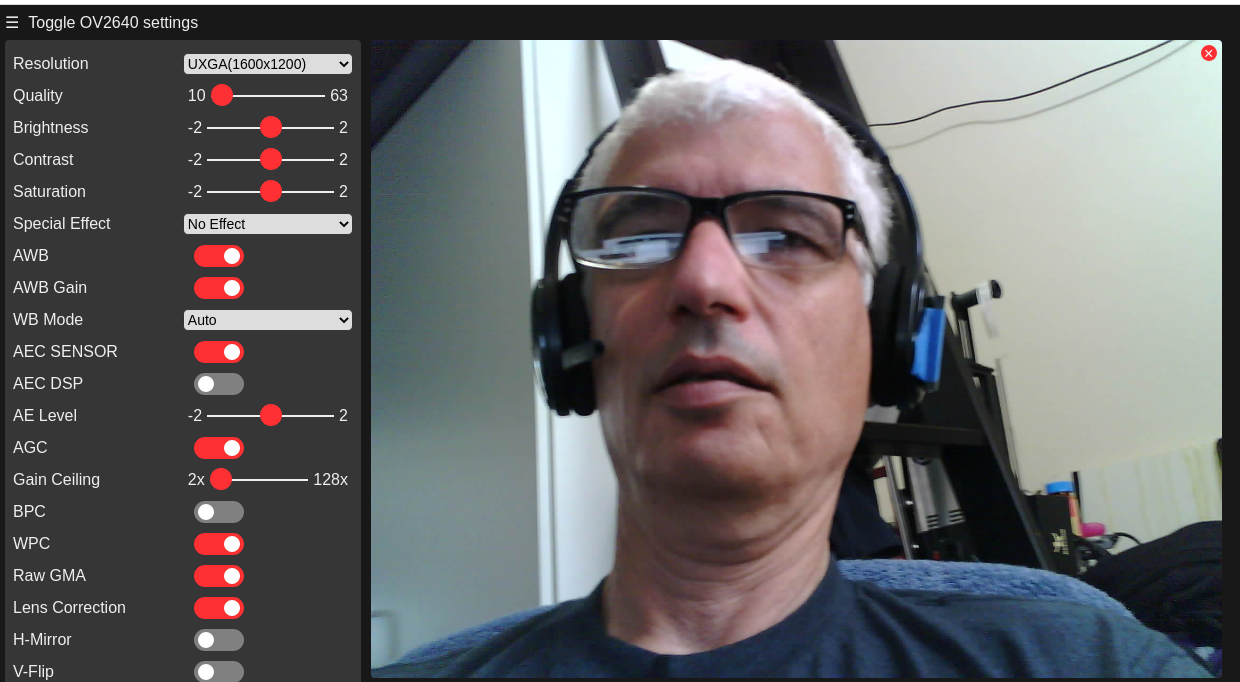
Also was able to get the ESP32-CAM working. I connected it to my laptop
to a USB 3 port. Uploaded code that connects it to my wifi and starts a streaming webpage. To upload code you have to put the ESP into programming mode. Short pin IO0 to ground (they are adjacent to each other and one pin from the
serial pins) and tap the reset button (when the serial monitor shows "connecting...")
Thomas